
|
 |

|
|
|
|
|
|

It ain’t about how hard you can hit. Its about how hard you can get hit, and how much you can take, and keep moving forward, Rocky Balboa
In the study of differential equations, non-linear autonomous systems are of significant interest due to their complex and rich behaviors. Such systems can model a variety of real-world phenomena, including population dynamics, chemical reactions, and mechanical systems like pendulums.
An autonomous system is a system of differential equations where the independent variable (often time t) does not appear explicitly in the functions. The general form of a two-dimensional non-linear autonomous system is:
$\begin{cases} x' = f(x, y) \\\ y' = g(x, y) \end{cases}$
where f(x, y) and g(x, y) are non-linear functions governing the time evolution of the variables x and y. Our goal is to analyze the behavior of such systems by:
To illustrate these concepts, we will apply them to a specific example: the lightly damped pendulum.
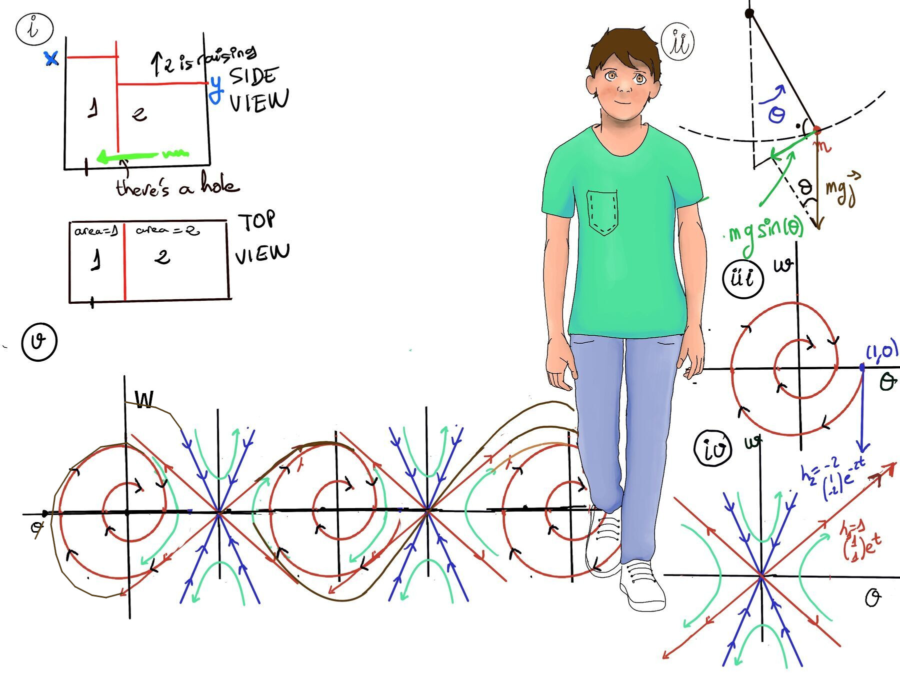
Consider a lightly damped pendulum, which consists of a mass m attached to a rod of length l swinging back and force under the influence of gravity and a damping force. The angle $\theta$ between the rod and the vertical axis describes the pendulum’s position (Refer to Figure ii for a visual representation and aid in understanding it).
Deriving the Equations of Motion
The dynamics of the pendulum’s motion are governed by Newton’s Second Law, which states that the net force acting on the pendulum in the tangential direction is equal to the mass times the angular acceleration, $m\vec{a} = \vec{F}$. Since linear acceleration $a$ along the circular path is related to angular acceleration $\theta''$ by $a = l\theta''$, we have: $m l \theta'' = \vec{F}$
The forces acting on the pendulum are:
Thus, Newton’s equation be $m l \theta'' = -mg\sin(\theta) - c_1 l \theta'$
By dividing everything by $m l$, we simplify this to: $\theta'' + \frac{c_1}{m}\theta' + \frac{g}{l}\sin(\theta) = 0$
To make the notation more compact, we define constants $c = \frac{c_1}{m}$ (the damping ratio) and $k = \frac{g}{l}$ (related to the natural frequency of the pendulum). This yields the non-linear second-order differential equation: $\theta'' + c\theta' + k\sin(\theta) = 0$
It is non-linear specifically due to the $\sin(\theta)$ term.
To analyze this system, we convert it into a first-order system by introducing a new variable $w = \theta'$ (the angular velocity).
Differentiating our new variable gives $w' = \theta''$. Substituting this into our simplified Newton’s equation gives: $w' = -k\sin(\theta) - c\theta' = -k\sin(\theta) - cw$
This leads to the following system of equations:
$$\begin{cases} \theta' = w \\ w' = -k\sin(\theta) - cw \end{cases}$$This is now a system of two first-order equations in the variables $\theta$ and $w$.
For this example, we will examine a specific under-damped (lightly damped) case, where $c = 1$ and $k = 2$. The system becomes:
$$\begin{cases} \theta' = w \\ w' = -2\sin(\theta) - w \end{cases}$$Step 1: Find Critical Points
Critical points (equilibrium points) are points where both derivatives are zero, i.e., where the system is in equilibrium (in a state of rest). Setting the right-hand sides of both equations to zero:
$\begin{cases} f(x, y) = 0 \\\ g(x, y) = 0 \end{cases}$
In our example, we need to solve:
$\begin{cases} w = 0 \\\ -2\sin(\theta) - w = 0 \end{cases}$
Substituting $w = 0$ into the second equation yields: $-2\sin(\theta) = 0 \implies \sin(\theta) = 0$
The solutions for this are $\theta = n\pi$, where $n \in \mathbb{Z}$. Thus, the critical points are $(\theta, w) = (n\pi, 0)$. These correspond to the pendulum being perfectly at rest ($\theta' = 0$) at various angles: $0, \pm\pi, \pm2\pi, \dots$
Physically, there are two notable types of critical points:
Step 2: Linearizing the System Near the Critical Points
To analyze the behavior near each critical point, we linearize the system. This could involve approximating the non-linear functions with linear ones by taking their Taylor expansion around the critical point. Near $\theta = 0$, we can use the approximation $\sin(\theta) \approx \theta$. The system then becomes:
$\begin{cases} \theta' = w \\\ w' = -2\theta -w\end{cases}$
This is a linear system and can be written in matrix form as:
$(\begin{smallmatrix}\theta'\\\ w'\end{smallmatrix}) = (\begin{smallmatrix}0 & 1\\\ -2 & -1\end{smallmatrix})(\begin{smallmatrix}\theta\\\ w\end{smallmatrix})$
To determine the behavior of the system, we calculate the eigenvalues of the matrix. The characteristic equation is:
$det(\begin{smallmatrix}0-λ & 1\\\ -2 & -1-λ\end{smallmatrix}) = (−λ)(−1−λ)−(−2)(1)=λ(λ+1)−(−2)= λ^2 + λ +2 = 0 ↭ λ = \frac{-1±\sqrt{1-8}}{2} = \frac{-1±\sqrt{-7}}{2}=\frac{-1±i\sqrt{7}}{2}$.
The eigenvalues are complex with a negative real part indicating a spiral sink.
Thus, near $(\theta, w)= (0, 0)$, the system exhibits a stable spiral or spiral sink. Trajectories spiral inward in a clockwise or counterclockwise fashion, depending on initial conditions, representing damped oscillations of the pendulum returning gradually to the equilibrium position (to rest at the bottom).
The motion of the pendulum will involve spirals that gradually shrink in size, representing the damping effect. The negative real part leads to the shrinking (loss of energy), while the oscillations correspond to the spiraling (swinging back and forth) until it returns to rest at the bottom.
Consider $(\theta, w) = (1, 0)$, $(\begin{smallmatrix}\theta'\\\ w'\end{smallmatrix}) = (\begin{smallmatrix}0 & 1\\\ -2 & -1\end{smallmatrix})(\begin{smallmatrix}\theta\\\ w\end{smallmatrix}) = (\begin{smallmatrix}0 & 1\\\ -2 & -1\end{smallmatrix})(\begin{smallmatrix}1\\\ 0\end{smallmatrix}) = (\begin{smallmatrix}0\\\ -2\end{smallmatrix})$
This show that the velocity is pulling downwards, so the motion is clockwise. Near (0, 0), the system exhibits spiral sinks, with trajectories spiraling inward in a clockwise direction. (Refer to Figure iii for a visual representation and aid in understanding it)
Behavior Around $(\pi, 0)$. At $(\pi, 0)$ we cannot approximate $\sin(\theta)$ as $\theta$. We compute the Jacobian matrix, which effectively linearizes the system by taking the multivariable Taylor expansion around the critical points.:
For a system:
$\begin{cases} \theta^′ = f(\theta, w) \\\ w^′ = g(\theta, w) \end{cases}$
The Jacobian matrix at a critical point $(\theta_0, w_0)$ is:
$J(\theta, w) = (\begin{matrix}\frac{\partial f}{\partial \theta} & \frac{\partial f}{\partial w}\\\ \frac{\partial g}{\partial \theta} & \frac{\partial g}{\partial w}\end{matrix})\bigg|_{\theta_0, w_0} = (\begin{matrix}f_\theta & f_w\\\ g_\theta & g_w\end{matrix})\bigg|_{\theta_0, w_0}$, and this is the matrix of the linearized system.
$(\begin{matrix}\frac{∂w}{∂θ} & \frac{∂w}{∂w}\\\ \frac{∂(-2sin(θ)-w)}{∂θ} & \frac{∂(-2sin(θ)-w)}{∂w}\end{matrix}) = (\begin{matrix}0 & 1\\\ -2cos(θ) & -1\end{matrix})$
Evaluate at (0, 0): $J_{(0, 0)} = (\begin{matrix}0 & 1\\\ -2 & -1\end{matrix})$. This is consistent with the previous result.
Evaluating the Jacobian at the inverted position gives: $(\pi, 0)$: $J(\pi, 0) = \begin{pmatrix} 0 & 1 \\ -2\cos(\pi) & -1 \end{pmatrix} = \begin{pmatrix} 0 & 1 \\ 2 & -1 \end{pmatrix}$
Finding the eigenvalues: $\det \begin{pmatrix} -\lambda & 1 \\ 2 & -1-\lambda \end{pmatrix} = (-\lambda)(-1-\lambda) - (2)(1) = \lambda^2 + \lambda - 2 = 0$
Factoring yields $(\lambda + 2)(\lambda - 1) = 0$, giving eigenvalues $\lambda_1 = 1$ and $\lambda_2 = -2$.
Having real eigenvalues with opposite signs strictly indicates a saddle point.
$\lambda = 1, (J-\lambda I)\vec{v} = \vec{0} ↭ (\begin{smallmatrix}-1 & 1\\\ 2 & -2\end{smallmatrix})(\begin{smallmatrix}a_1\\\ a_2\end{smallmatrix}) = \vec{0}$
$\begin{cases} -a_1 + a_2 = 0 \\\ 2a_1 -2a_2 = 0 \end{cases}$
$-a_1 + a_2 = 0 \implies a_1 = a_2 =[\text{Simplicity}] 1$. The second equation is redundant. Eigenvector: $(\begin{smallmatrix}1\\\ 1\end{smallmatrix})$. The solution is $(\begin{smallmatrix}1\\\ 1\end{smallmatrix})e^{t}$
$\lambda = -2, (J-\lambda I)\vec{v} = \vec{0} ↭ (\begin{smallmatrix}2 & 1\\\ 2 & 1\end{smallmatrix})(\begin{smallmatrix}a_1\\\ a_2\end{smallmatrix}) = \vec{0}$
$\begin{cases} 2a_1 + a_2 = 0 \\\ 2a_1 + a_2 = 0 \end{cases}$
$2a_1 + a_2 = 0 \implies a_2 = -2a_1$. Eigenvector: $(\begin{smallmatrix}1\\\ -2\end{smallmatrix})$. The solution is $(\begin{smallmatrix}1\\\ -2\end{smallmatrix})e^{-2t}$
The eigenvalues are real and have opposite signs. This indicates a saddle point at $(\pi, 0)$. The general solution is $\boxed{c_1(\begin{smallmatrix}1\\\ 1\end{smallmatrix})e^{t}+c_2(\begin{smallmatrix}1\\\ -2\end{smallmatrix})e^{-2t}}$
Near $(\pi, 0)$, the system exhibits a saddle point, with trajectories diverging in one direction and converging in another (Refer to Figure iv for a visual representation and aid in understanding it).
Step 3. Plot trajectories around each critical point and then add some more. (Refer to Figure v for a visual representation and aid in understanding it)
The global behavior demonstrates the periodic nature of the pendulum system (since $\sin(\theta)$ is periodic with period $2\pi$), with repeated critical points at multiples of $\theta, \theta = n\pi$ alternating between stable spirals (damped oscillations) and saddle points (more complex behavior).

JustToThePoint Copyright © 2011 - 2026 Anawim. ALL RIGHTS RESERVED. Bilingual e-books, articles, and videos to help your child and your entire family succeed, develop a healthy lifestyle, and have a lot of fun. Social Issues, Join us.
This website uses cookies to improve your navigation experience.
By continuing, you are consenting to our
use of cookies, in accordance with our Cookies Policy and
Website Terms and Conditions of use.