
|
 |

|
|
|
|
|
|
You have enemies? Good. That means you’ve stood up for something, sometime in your life, Winston Churchill
Definition. A differential equation is an equation that involves one or more dependent variables, their derivatives with respect to one or more independent variables, and the independent variables themselves, e.g., $\frac{dy}{dx} = 3x +5y, y' + y = 4xcos(2x), \frac{dy}{dx} = x^2y+y, etc.$
It involves (e.g., $\frac{dy}{dx} = 3x +5y$):

In mathematics, a linear ordinary differential equation (ODE) is an equation involving an unknown function and its derivatives, characterized by the property that both the function and its derivatives appear linearly. This means that the unknown function and its derivatives are raised only to the first power. They are never multiplied together, nor are they composed within nonlinear functions (such as $\sin(y)$ or $e^y$). The general form for a first-order linear ODE is: a(x)y’ + b(x)y = c(x).
This property of linearity is fundamental. While most physical systems are inherently nonlinear, many can be accurately approximated by linear models over a specific range. This linearity allows mathematicians and engineers to utilize a vast and powerful toolkit of analytical solution methods that are unavailable for nonlinear systems. Consequently, linear ODEs are the bedrock of modeling in numerous fields, including:
In this article, we will explore different forms of linear ODEs, their applications, and their solutions, with a focus on understanding their behavior in real-world contexts.
An ODE of order n is linear if it can be expressed in the form: $a_n(t)\frac{d^ny}{dt^n} +a_{n-1}(t)\frac{d^{n-1}y}{dt^{n-1}} + ··· + a_1(t)\frac{dy}{dt} + a_0(t)y = q(t)$ where
The function y and its derivatives appear to the first power and are not multiplied together.
In this second article, we will continue exploring different forms of linear ODEs, their applications, and their solutions, with a focus on understanding their behavior in real-world contexts.

An RC circuit is a fundamental electrical circuit combining a resistor (R) and a capacitor (C) connected in series or parallel with a voltage source. Understanding the behavior of an RC circuit is crucial in fields like electrical engineering and physics because it illustrates how circuits respond over time to changes in voltage. This response is characterized by the charging and discharging of the capacitor, which is governed by a first-order linear ordinary differential equation (ODE).
In an RC circuit, the relationship between the charge q(t) on the capacitor, the current i(t), and the applied voltage ε(t) is governed by the following first-order linear ordinary differential equation (ODE): $R\frac{dq}{dt}+\frac{q(t)}{C}=ε(t)$ where:
This equation is derived by applying cornerstone circuit laws:
$V_R + V_C = ε(t)$ ↭[Substitute VR (Ohm’s Law) and VC (Voltage Across Capacitor):] $\boxed{R·\frac{dq}{dt} + \frac{q(t)}{C} = ε(t)}$
This is a first-order linear ordinary differential equation, describing the dynamically evolving charge q(t). The time-varying current is implicitly captured by $\frac{dq}{dt}$, meaning the circuit’s overall response is characterized by the charging and discharging of the capacitor.
To solve the differential equation, we rewrite it in standard linear form: $\frac{dq}{dt}+\frac{1}{RC}q = \frac{ε(t)}{R}$.
Using the notation q’ = $\frac{dq}{dt},\text{ we have } q' +\frac{1}{RC}q = \frac{ε(t)}{R}$
This equation is a first-order linear ordinary differential equation, which can be solved using an integrating factor.
The general solution q(t) consists of two components:
For a constant voltage source, the specific solution, incorporating the natural and forced responses, is explicitly derived:
The resulting dynamic current i(t) is simply the derivative: i(t) = $\frac{dq}{dt} = \frac{d}{dt}(EC) + \frac{d}{dt}((q_0 -EC)e^{\frac{-t}{RC}}) = 0 +(q_0 -EC)\frac{-1}{RC}e^{\frac{-t}{RC}} = -\frac{q_0 -EC}{RC}e^{\frac{-t}{RC}}$.
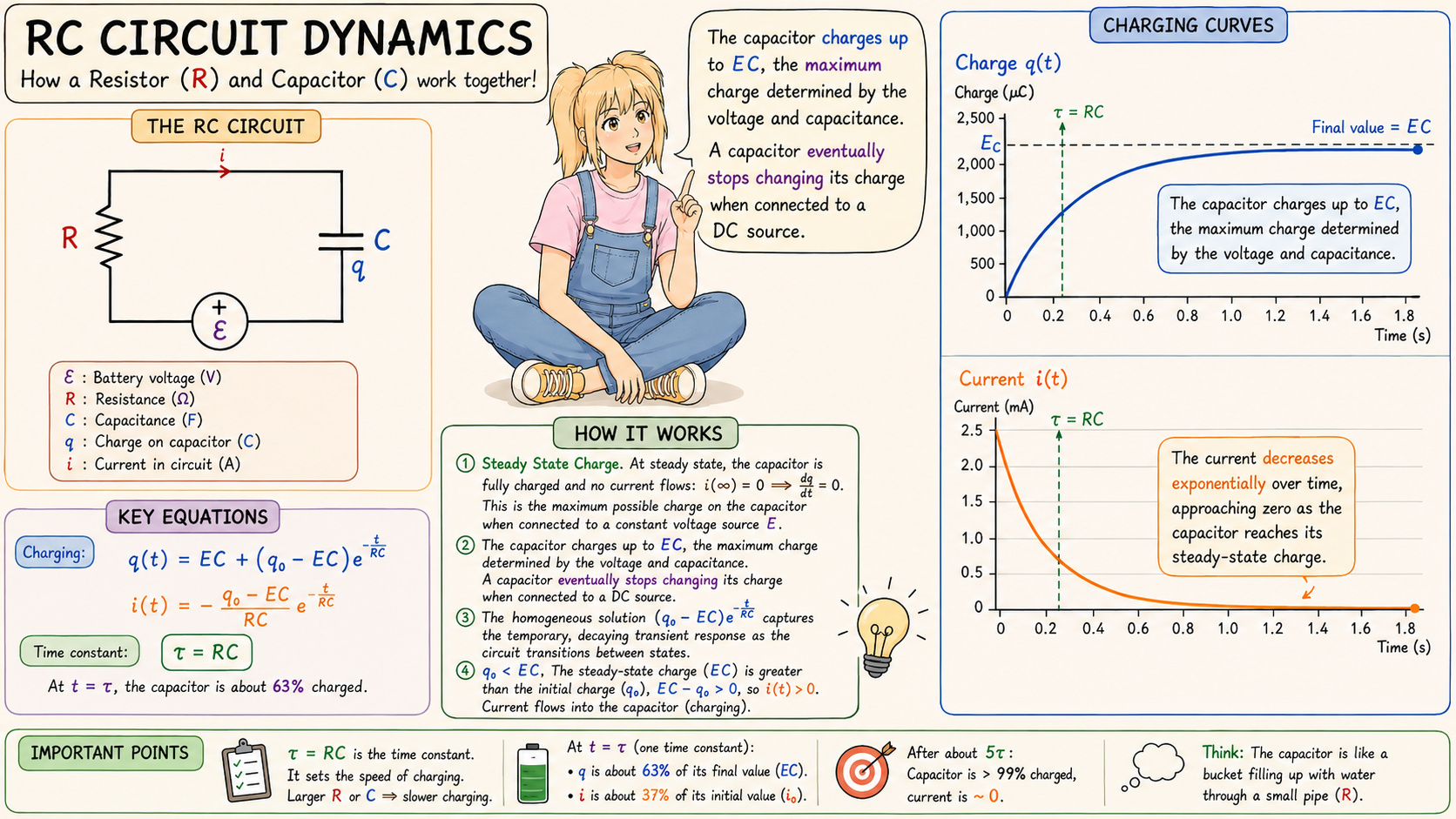
Steady State Charge, $q_{SS} = EC$.
At steady state, the capacitor is fully charged and no current flows: $i(\infty) = 0 \implies \frac{dq}{dt} = 0$.
Plug this into the ODE: $R \cdot 0 + \frac{q_{\infty}}{C} = E \implies q_{\infty} = EC$. This is the maximum possible charge on the capacitor when connected to a constant voltage source 𝐸.
🧩 It depends only on the voltage and the capacitance. It does not depend on the resistance 𝑅. Resistance only controls how fast you get there.
As time progresses indefinitely ($t \to \infty$), the exponential term $e^{-\frac{t}{RC}}$ approaches zero. The homogeneous natural response decays completely. The capacitor dynamically approaches a steady-state charge, The capacitor charges up to EC, the maximum charge determined by the voltage and capacitance. $q(t) \to EC, i(t) \to 0$. A capacitor eventually stops changing its charge when connected to a DC source. No change in charge → no current.
Transient Behavior: The homogeneous solution $(q_0 -EC)e^{\frac{-t}{RC}}$ captures the temporary, decaying transient response as the circuit transitions between states. The direction and magnitude of the current change are indicates how much of a current will flow into or out of the capacitor dynamically:
($\star$) Charging. $q_0 \lt EC$. The steady-state charge (EC) is greater than the initial charge ($q_0$), $EC - q_0 \gt 0$, so i(t) > 0. Current flows into the capacitor (charging), increasing its charge towards EC. The current decreases exponentially over time, approaching zero as the capacitor reaches its steady-state charge.
($\star$) Discharging. $q_0 \gt EC$. The steady-state charge is smaller than the initial charge, $EC - q_0 \lt 0$, so i(t) < 0. Current flows out of the capacitor, reducing its stored charge towards EC. In both cases, the exponential term shrinks, so the current decays to zero.
The time constant τ is a key parameter: τ = RC. It determines the rate at which the capacitor charges or discharges.
The larger the resistance or capacitance, the longer it takes for charge to build or decay. After one time constant (t = τ), the transient term decays to approximately $e^{\frac{-t}{RC}} = e^{-1} ≈0.3679$, meaning the process is roughly 1 - 0.37 = 63% complete.
In other words, the capacitor has completed 63% of the journey toward steady state.
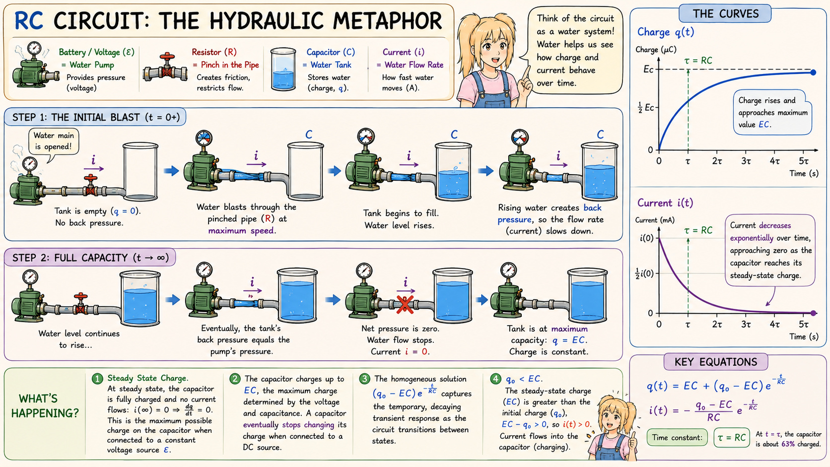
The most powerful way to visualize this is as a filling tank broken down into chronological steps.
The Battery / Voltage (ε) is the Water Pump: It provides the “pressure” (voltage) pushing the water (electrons) through the system.
The Resistor (R) is a Pinch in the Pipe: A narrow section of pipe creates friction, restricting how much water can flow through at once. A higher resistance means a narrower pipe.
The Capacitor (C) is a Water Tank: As water flows in, the tank fills up (storing charge, q).
Current (i) is the Water Flow Rate: It is how fast the water is moving through the pipes at any given second.
The cartoon infographic helps you map these specific behaviors to the components:
Step 1: The Initial Blast: The water main is opened. The storage tank is empty, so there is zero back pressure. Water blasts through the pinched pipe (the resistor) at maximum speed. This is the high-flow point on the Current graph.
Filling Chronology (The curves): As water flows in, the water level in the tank rises (Charge curves up). But as it rises, that water creates its own pressure, pushing back against the pump. Since the net pressure in the system is dropping, the current flow must slow down (Current curves down).
Step 2: Full Capacity: Eventually, the tank’s back pressure exactly matches the pump’s forward pressure. The net pressure is zero. The water flow stops entirely (Current is zero), and the tank is sitting at its maximum capacity (Charge is flat/constant).

JustToThePoint Copyright © 2011 - 2026 Anawim. ALL RIGHTS RESERVED. Bilingual e-books, articles, and videos to help your child and your entire family succeed, develop a healthy lifestyle, and have a lot of fun. Social Issues, Join us.
This website uses cookies to improve your navigation experience.
By continuing, you are consenting to our
use of cookies, in accordance with our Cookies Policy and
Website Terms and Conditions of use.